The service factor of an electric motor indicates its ability to handle temporary overload conditions without damage. It's expressed as a multiplier, and you can calculate the allowable overload horsepower using the following formula:
\[ \text{Allowable Overload HP} = \text{Rated HP} \times \text{Service Factor} \]
Brake horsepower (BHP) for pump selection is calculated using the formula:
\[ BHP = \frac{{Q \times H}}{{3,960 \times \eta}} \]
Where:
To determine the required motor size using the service factor, you can use the following formula:
\[ \text{Required Motor Size (HP)} = \frac{{BHP}}{{\text{Service Factor}}} \]
For example, if the calculated BHP for a pump is 10 HP and the motor's service factor is 1.15:
\[ \text{Required Motor Size (HP)} = \frac{{10\ HP}}{{1.15}} \approx 8.70\ HP \]
You would need a motor with a rated capacity of at least 8.70 HP, rounded up for practical purposes.
For this example, we are using a T31 Series pump. However, this selection method is applicable to all regenerative turbine pumps.
CAUTION: The service factor, often interchangeably termed "Safety Factor," should only be applied if the application necessitates a motor with different specifications that wouldn't have the same service factor. Numerous OEM applications employ service factors due to pre-established parameters and physical size restrictions.
A T31G pump is chosen to operate at 200 feet, yielding 4 gallons per minute. The brake horsepower at this head capacity is calculated at 0.6 BHP.
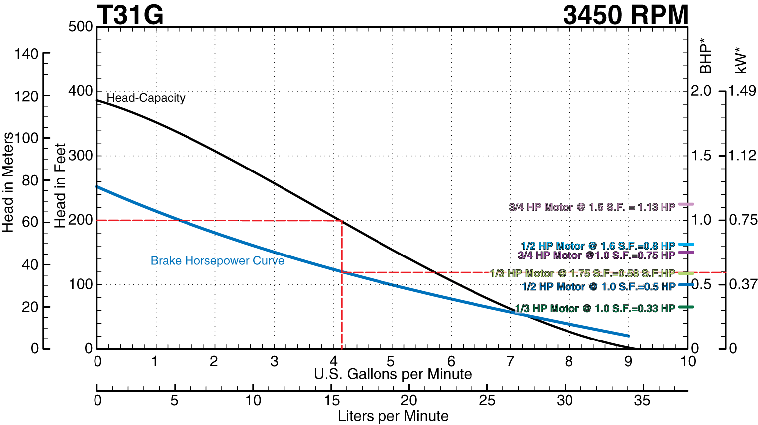
With a 1.0 service factor motor, a 3/4 HP motor would be necessary to meet the marked Head-Capacity.
A 1/3 horsepower motor boasting a 1.75 service factor is evaluated. Using the service factor, the maximum brake horsepower before the motor overamps is pegged at 0.58 horsepower. However, the T31G with a 1/3 HP motor would overamp at 200 feet of pressure, producing approximately 4 GPM.
A 1/2 horsepower motor equipped with a 1.60 service factor is examined. By leveraging the service factor, the maximum brake horsepower before the motor overamps is capped at 0.8 horsepower.
The MTH C Series centrifugal pumps are engineered to function from shutoff to runout without overamping the custom motor specifically employed in this pump series. When selecting a C Series pump mounted on a bearing pedestal or 56C Face adapter, motor selection necessitates adherence to a 1.0 service factor, often resulting in a larger motor than the standard close-coupled configuration.
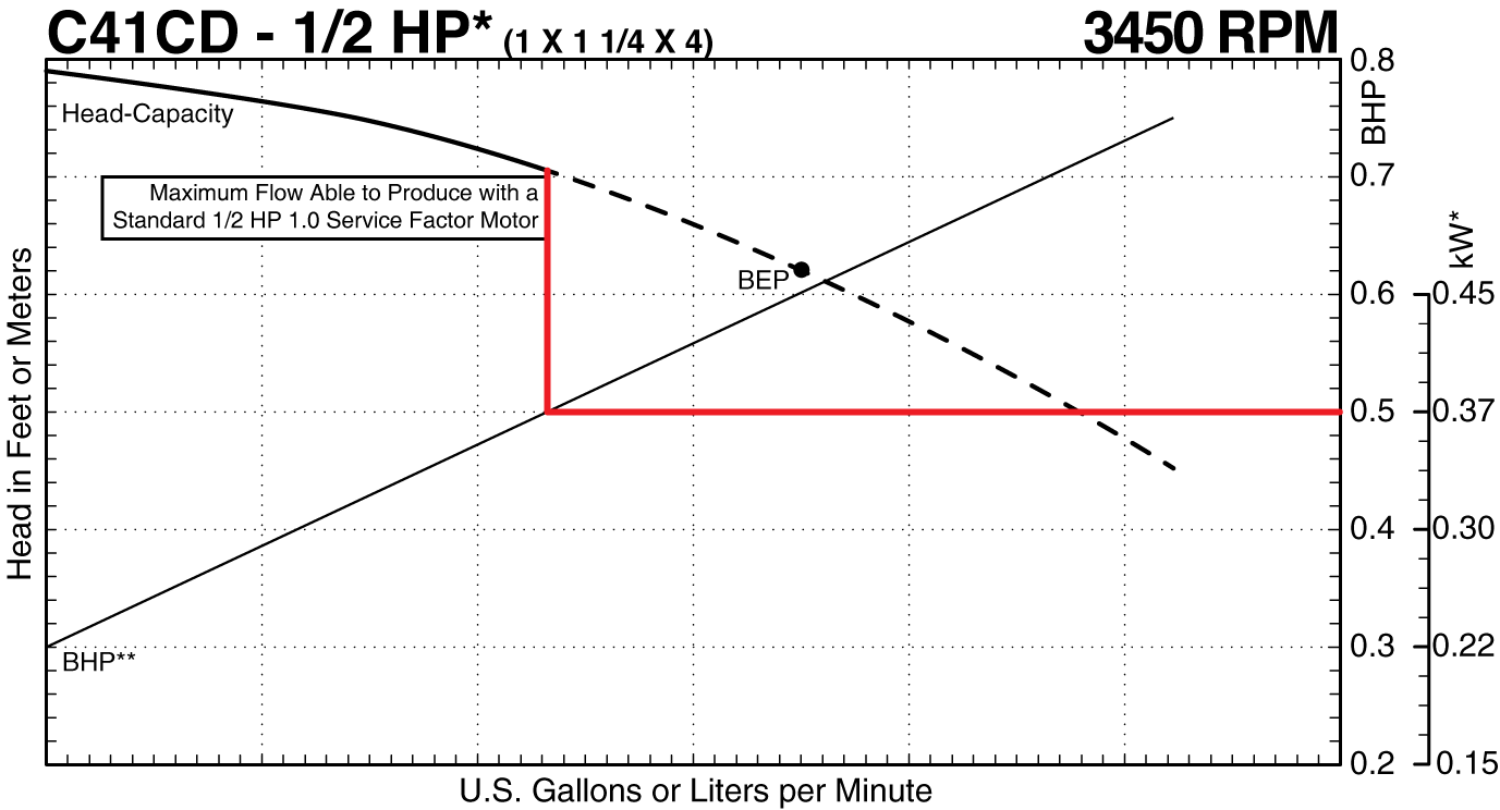
In a specific case, let's take a C41CD configured with a standard 80/42 Frame D3 (Dual Faced) Style Motors 1/2 HP motor boasting a 1.6 service factor.
This motor can drive a pump up to 0.8 brake horsepower without surpassing the manufacturer's rated full load amps. Operating within the service factor range enables the pump to function from less than 0.3 brake horsepower at shutoff to approximately 0.75 brake horsepower at runout.
However, if the C41CD pump were mounted to a bearing pedestal or 56C face adapter, utilizing a 1.0 service factor motor, the maximum flow would be constrained unless opting for a 3/4 HP motor.


